
|
|
|
|
|||||||
| General Discussion (Everything Else) Discuss anything that doesn't belong in any other forums here. |
 |
|
|
Thread Tools | Display Modes |
|
#2
 04-16-2014, 06:44 AM
|
||||
|
||||
|
Stumped us lol

|
|
#3
04-16-2014, 07:52 AM
|
||||
|
||||
|
The portion on Active sonar was closest to your question, still a little vague though.
http://en.m.wikibooks.org/wiki/Acoustics/Sonar I think a sounder is the device, echo is the bounce back, and chirp is a type of signal/sound that the sounder would send out and provide data based on the echo...
|
|
#4
04-16-2014, 08:02 AM
|
||||
|
||||
|
regular sonar just sends one frequency at a time, chirp sends a continuous sweep of frequencies so it produces a clearer image. Its really only useful offshore
|
|
#5
04-16-2014, 08:08 AM
|
||||
|
||||
|
a sounder is the device that receives the data, it can either be a standard or chirp enabled device
|
|
#6
04-16-2014, 08:39 AM
|
||||
|
||||
|
Hi guys. For the last few weeks I have been researching the latest in echo sounders/fish finders. Having been away from the market for a few years since I got my first generation digital sounder from Raymarine (DSM 250), I was pleasantly surprised to see breakthrough technology such as CHIRP Sounders. Alas, I could find very little real technical data on their performance. All I see are one-pager marketing brochures with very little real technical data. The best source of info was actually this forum. I have learned a lot from reading the posts here but the total picture still remained fuzzy. So I set out to research the field on my own and have managed to gather useful data on how well these systems may perform. I thought I share that with you all in this post. As a way of background, I am an electrical engineer with a few decades of experience in audio/video/computing fields. Those skills don’t necessary translate well to understanding sounder technologies but I also happen to have a specialty in room acoustics and signal processing which do have a decent overlap (see some of the articles I have written here: http://www.madronadigital.com/Library/Library.html). That familiarity allowed me to dig in and get a far better grasp of CHIRP technology than reading the marketing brochures from manufacturers. That said, you don’t become an expert in a new field by just reading things for a few weeks  . So while you hopefully see fair amount of explanation to follow on sounder technology, I don’t put them forth as authoritative. There may be mistakes in my analysis and certainly some holes as I will describe later. I look forward to feedback from you all to complete the picture and update this post accordingly. Thanks in advance. . So while you hopefully see fair amount of explanation to follow on sounder technology, I don’t put them forth as authoritative. There may be mistakes in my analysis and certainly some holes as I will describe later. I look forward to feedback from you all to complete the picture and update this post accordingly. Thanks in advance.Background Understanding the value of CHIRP requires first learning how traditional echo sounders work and their limitations which CHIRP sets out to solve. Fortunately pulse sounders as I call them are very simple devices as far as theory is concerned. A short pulse of a single frequency is sent out using a transducer and then we listen to see how long it takes to get a reflection back. The returned data has timing which tells us how far away the “target” is from the transducer and an amplitude number which tells us something about its characteristics. These two pieces of data is plotted on an LCD screen and we get our echo sounder. Those two pieces of data also set the limits of our sounder performance: 1. Range Resolution This is a metric that says how well we can distinguish targets that are close to each other. A range resolution of say, 3 feet, would mean that multiple targets within 3 feet would be rendered as one. Computing range resolution is pretty easy as it is completely proportional to our pulse length. All we have to do is multiply the pulse lengthy by the speed of sound in water, divide by two and we arrive at a distance. That distance is our minimum range resolution. For example, if our pulse (ping) is 0.5 milliseconds (0.0005 seconds), our range resolution is 1.28 feet (0.0005 * 5118 / 2). Here is a good visualization of what happens when the targets are separate or too close to be distinguished: 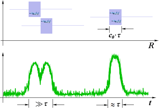 On the left the targets are separated enough to be seen as two bumps. The two on the right are shown as a single return since they are too close together (this is a radar image so shows targets horizontally but the concept is the same). Note that frequency that we use within that pulse has nothing to do with this. Only the pulse length determines the range resolution. You might ask why we don’t make the pulse smaller to improve our resolution. Problem there is power. Remember that the amplitude of the return pulse is something of interest to us. That pulse needs to rise up above the level of noise (see next section). If we shorten the pulse, we proportionally reduce the amount of power we put in the water to detect target. If in the above example we made our pulse 10 times smaller to have 0.128 feet/1.5 inch of range resolution, we would wind up with just 10% of the power. That would sharply reduce our range. We could compensate by boosting power but that increases the burden on the transducer which now has to handle much higher peak power. See more in later section. One compromise may be to have adaptive pulse lengths. Keep them short for good shallow range resolution but lengthen them in deep water. The latter will give us the power to penetrate deep at the expense of losing resolution. Note that once you use longer pulses, you lose resolution there at all water depths. All targets suffer in that body of water relative to resolution. So what is the pulse length of your sounder? Amazing as it may sound, it is rarely documented in recreational sounders. And with some exceptions (such as a Koden sounder I found), no control is given to the user to adjust on his own. Fortunately this becomes a moot point with CHIRP sounders as I explain later. 2. Target Resolution This is my term to describe what size targets we can resolve. A fundamental principal in acoustics says that to get a reflection, the target needs to be larger than the wavelength of our sound wave. What is a wavelength? Single frequency tones repeat on a cycle. The Wavelength is the distance at which the wave repeats: 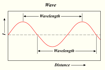 The wavelength is computed easily by taking the speed of the wave through our medium and dividing it by frequency. As you know, one of the common frequencies in sounders is 50 KHz. Sound travels through salt water at around 5118 ft/sec which makes our wavelength 1.2 inches. When a target is smaller than this, the sound refracts around it as if it is not there. Think of taking a 1 inch water hose and putting your finger in the middle of the water stream. You will notice that little reflects back as the bulk travels around your finger. Now put the palm of your hand in front of it and almost all the water bounces back. Similar concept here. A closer example is to put your hand in front of the tweeter on your speaker. You immediately hear the effect in how the high frequencies become muffled. Now do the same on the woofer and you will not notice much reduction. The longer sound waves of the frequencies from the woofer don’t “see” your hand as their wavelength is many feet and therefore travel around your hand. The ones from twitter are an inch or two and hence get reflected. Higher frequencies are therefore available to increase our resolution in this regard. At 200 KHz, our wavelength drops to 0.3 inches. At 455/800 KHz which are frequencies used for structure and side scan sounders, the number drops yet again to 0.13 and 0.08 inches respectively. So why not use the higher frequencies all the time? Well, there is no free lunch here and our depth ability suffers as frequencies go up. Salt water is a good sound transmission medium at lower frequencies but not high. This is an insidious problem because our sound not only needs to make it down to our target, but also return back to us to measure it, doubling any losses! Computing exact losses are difficult but a lot of experimentation has given us approximations which you can find in online calculators. Using common parameters (e.g. 20 degree C temp and typical salinity of salt water), we get these numbers for signal loss (in Decibels) per 1000 feet of water column (multiplied by two to account for roundtrip loss): 50 KHz: 5 dB 200 KHz: 49 dB 455 KHz: 88 dB 800 KHz: 152 dB As we see, the losses become staggering as frequencies go up. What do you say? Boost the power to make up for the losses? Well, if you double the power, you only gain 3 dB improvement (decibels are in logarithm scale). You need about 100,000 times more power for the 200 KHz wave to have the same energy at the end of that 2000 feet round-trip as 50 KHz! Now we know why our structure and side scanners have much more limited range than our lower frequency sounders. BTW, one way to cheat is to have a narrower beam as frequencies go up. This focuses the energy more (higher “directivity”) and like focusing a light beam, gives us more equivalent power. Side-scan and structure scan transducers do this to an extreme with very narrow angle in one direction and standard transducers do the same by narrowing the high frequency beam. The latter comes at the cost of reduced coverage of area that the beam sees. While we are computing losses, we should also compute the main factor which is distance related. As the sound waves move away from the transducer, they literally balloon in size. They keep expanding and that expansion means we lose energy per unit of surface area. The loss is 6 decibels per doubling of distance. Computing the same loss for 1000 feet deep target, we get a loss of 37 dB. This loss is frequency independent and would need to be added to the numbers above to get our combined loss. For the 50 KHz signal depth dominates compared to frequency related loss (37 dB vs. 5 dB). When we jump to 200 KHz, the frequency dependent losses become very significant at 49 dB for a total of 37+49 = 86 dB compared to just 43 dB for 50 KHz. A quick summary then is that your sounder has two metrics of resolution: one that is based on the path between the transducer and the target. And the other, is how large of a target you can resolve. You have had some control of the latter by choosing your sounder frequency but not the former. Note also that these are absolute limits of performance. What you actually get is degraded from these due to equipment limitations. Now that I have gotten you sufficiently depressed over how sounders work , let me give you some relief with respect to this new CHIRP technology.CHIRP Technology As you may have heard, CHIRP technology was originally developed for radars. The term stands for ” Compressed High Impact Radar Pulse.” Its development dates back to classified work and use during WWII era. The technique became declassified around 1960 so its use became widespread including application in sounders. The needs of the two domains are very similar as radars and fish finders both care about discriminating between targets and having good distance performance. So what is the idea here? Recall that we detected the range/distance to our target in traditional pulse sounders using time. We measured how long it took for the pulse to return to us and that told us the distance since we know the propagation speed of sound through water. CHRIP replaces time with frequency. We still have a pulse. But within that pulse, we don’t use one frequency but rather, a range of frequencies. Instead of 50 KHz tone, we start at 40 KHz and keep incrementing to 60 KHz before the pulse ends. To measure “distance” now, we look at which frequencies the target excites. In the example I just gave, we have 20,000 different frequencies. That gives us a lot of steps to use to resolve the distance from our target. A remarkable thing happens when we use a frequency sweep this way. Our range resolution becomes completely independent of pulse length! If I have 20,000 frequency steps, you can make the pulse 10 times bigger or smaller and I would still have that many steps. With standard pulse sounder which in this context is called a “narrow band” sounder (since it uses a single tone vs many in CHIRP), our resolution is = speed of sound in water * Pulse length / 2. With CHIRP, our resolution = speed of sound in water / (2 * Bandwidth). Bandwidth is the range of frequencies. In the above example of 40 to 60 KHz, we have 20,000 Hz (20 KHz) of bandwidth. Assuming a pulse length of 0.5 millisecond, our standard sounder has a range resolution of 1.28 feet or 15 inches. A CHIRP sounder using the same pulse but with that 20 KHz of bandwidth will shrink that number to just 1.5 inches!!! This is why you see statements like this in the Simrad BSM-2 brochure: ”Your ability to resolve individual fish, or separate fish from bottom structure, is now a matter of inches, instead of several feet with traditional fishfinders. See individual fish in groups, instead of a single mass.” Indeed we have taken our range resolution from unit of feet to unit of inches. The several feet part comes if you use longer pulse than my example above which reduces the range resolution of pulse sounders but not CHIRP. CHIRP Gain In the above example, if we divide 15 inches by 1.5, we get a figure of merit of 10. That is the gain in range resolution achieved by using CHIRP. Our pulse got “compressed” by that factor. I put compressed in quotes because our pulse has not really shrunk. The sounder is still sending the same pulse length as it would have if CHIRP was not used. But from practical point of view the system is acting as if its pulse had shrunk proportional to the bandwidth of our CHIRP frequencies. Mathematically we can compute the gain by multiplying our pulse width by the bandwidth. In our example, 0.5 milliseconds is 0.0005 which times 20,000 gives us the same gain of 10. This analysis gives us one of the key metrics in CHIRP performance: system bandwidth. We saw how the CHIRP sounder resolution is computed by taking speed of sound in water and dividing it by two times bandwidth. Life gets better and better as our bandwidth increases. Let’s take the “high CHIRP” range of frequencies available to us in new CHIRP sounders at 130 KHz to 210 KHz. The bandwidth is the difference between them or 80 KHz. Performing the math results in amazing range resolution of just 0.4 inches! Our CHIRP gain using the same 0.5 msec example as before has jumped from 10 (for the 40 to 60 KHz range) to 40 (for 130 to 210 KHz). Note that improved target resolution works at all depths/distances. In the above example, you would have a target resolution of 0.4 inches whether you are in 10 feet of water or 10,000. A traditional sounder may increase its pulse length to penetrate deeper water, which puts it at even worse disadvantage compared to CHIRP. For this reason, often people think of CHIRP as a deep water technology but that is not correct. CHIRP will outperform a pulse sounder at all depths. CHIRP Power Expanding on the last topic, synonymous with CHIRP is this notion of increased power to penetrate deeper water. Yet the theory of CHIRP is all about range resolution. So how do we get more power to penetrate deeper water? The answer is simple: since CHIRP’s range resolution is not dependent on pulse length anymore, we are free to boost that as much as we like. As I noted earlier the power in the water is = output power * pulse width. If we have a 1,000 watt sounder and we pulse it at 1 msec, then the effective amount of power into water is 1000 * .001 = 1 watt. To get more power in the power we could increase the pulse length but then that reduces our resolution. We could increase the power sent to the transducer but that has a cost in power consumption and beefier transducer to handle the additional peak power. These problems go away with CHIRP. Pulse length can be increased with no ill effects on range resolution. So that becomes the ticket to get much better depth performance. The Simrad BSM-2 for example has a max pulse length of 70 milliseconds. If this were a conventional pulse sounder, the range resolution would be an ugly 179 feet! Anything within that column of water could not be separated than any other. Turn on CHIRP at high range with 80 KHz of bandwidth and our vertical resolution reduces to a remarkable 0.4 as if the pulse was very narrow. Taking the ratio of these two resolutions we see that our CHIRP gain is an incredible 1.5 million!!! In other words, if you wanted to build a traditional sounder that had the same 0.4 inch in resolution, its power would have had to be 1.4 million times higher to achieve the same performance as CHIRP. A traditional sounder may have a “long” pulse length of just 5 msec. Compared to that, our 70 msec pulse in the Simrad BSM-2 is 14 times longer. If the 5 msec sounder had 1,000 watts of power, we could outperform it with just 100 because that is equivalent to 100x14 = 1,400 watts. The 5 msec sounder will have a range resolution of 7.7 feet vs. our CHIRP sounder of 0.4 inches. All around greatness! The BSM-2 is rated at 250 watts by the way so using the same multiplier it would have a performance equiv. to 3,500 watts. As another example, the Raymarine CP450C has a pulse length of 80 msec which gives it a similar performance to Simrad BSM-2 with respect to resolution. They spec a “nominal power” rate of 1,000 watts. I have no idea what “nominal” means. If that is RMS power then it has four times the power of BSM-2. Alas, I could not find any specs for the maximum pulse length of Garmin GSD-26. Nor did I find such data for the Furuno DFF1-UHD. What is stated is that the Furuno has a high range is 175 KHz to 225 KHz which gives us a bandwidth of 50 KHz rather than 80 KHz in Simrad/Raymarine/Garmin. This degrades the target resolution from 0.4 inches to 0.6 inches. Not much to lose sleep over although it is interesting that they have gone for a shorter range here. Better be careful to pick a transducer also that is optimized for that range (i.e. maximum of 225 Khz vs 210). On the low range, Furuno specs +- 20 KHz which gives us double the bandwidth at 40 KHz (Simrad and others are 20 KHz). This shrinks the low CHIRP resolution form 1.5 inches to 0.8 inches. So it seems that is where Furuno is trying to differentiate by providing better target resolution at the low frequency range, in essence optimizing for deeper water performance. Performance Comparison For all the advantages of CHIRP, it is remarkable that there is no side-by-side comparison with older technology. Researching beyond recreational sounders I did find some good comparisons. Here is one from the paper, “FM slide (chirp) signals: a technique for significantly improving the signal-to-noise performance in hydroacosutic assessment systems” by Ehrenberg and Torkelson. Two systems are compared. One is a pulse based system with a pulse length of 0.18 millisecond giving it a range resolution of 5.5 inches (top row). The other is CHIRP with 10 KHz of bandwidth giving it a range resolution of 3.1 inches. So roughly equal in range resolution. The difference then is how much better the signal to noise ratio is due to longer 5 millisecond pulse length in CHIRP (bottom row):  The top row is traditional pulse sounder. The lower row is CHIRP. Notice the much longer pulse length in CHIRP which gives its much increased power in this comparison. There is only one target and is being shown in the form of that one spike in each graph (below the pulse line). Our goal is to get the cleanest pulse above the noise floor as to make it easy and clear for us to find our targets of interest (fish, structure, etc). The ratio of that peak of that spike and the variations around it is our "signal to noise ratio" or S/N for short. The higher the S/N, the better in electronic systems. The term "noise floor" is used to refer to average level of noise. The left pair is in the conditions of little noise (e.g. clear water and shallow depth). There is little to separate the performance of CHIRP vs pulse although the CHIRP is ever so slightly cleaner with respect to noise floor. The pair on the right represents addition of 10 dB worth of noise (e.g. due to deeper targets or higher frequency in use). The pulse sounder on top right shows immediate pain in the form of increased noise whereas the CHIRP in the bottom right is barely impacted with very clean return of that one target. Let’s increase the noise even more:  The increase of 10 more dB of noise creates havoc for the pulse system on top left. No longer can one tell where the target is as it is lost in sea of noise pulses. When noise is this high, turning up the volume, i.e. sounder gain, will do you no good since it will increase the level of noise and our target return at the same time so you will get a lot of clutter with your target lost in them. In sharp contrast to above, the CHIRP response on bottom left is going about its business, barely registering the noise. Our sharp target response is still there, well above the noise floor. Raising the noise another 10 dB finally pushes the CHIRP system to its limit although one can still make up the main target pulse as it has higher amplitude than noise (bottom right). The pulse system lost the battle in the last round and shows totally random response. We clearly see the benefits here: CHIRP while giving us slightly higher resolution (3.1 inches vs. 5.5), managed to provide 30+ dB of advantage in signal return over the pulse system. Such increased power can be put to use for example in the form of using the higher frequencies in our sounder at much lower depths. Or maintain bottom while at speed and deeper sea floor. Here is another example that I found online (click here for the larger image http://www.omg.unb.ca/Ksidescan/images/K320_chirp.gif): :  These are side-scan images using 200 KHz. The left is a traditional pulse system which as indicated, uses a 0.1 millisecond pulse. The middle image increases the pulse length to 3.0 milliseconds which smears the detail as expected. The right image is CHIRP. It keeps the same timing (slightly boosted to 3.2 milliseconds) but uses CHIRP with 8 KHz bandwidth. Even with that modest bandwidth there is sharply improved contrast which is the result of much better signal to noise ratio. We get superb resolution and signal strength. This is another good example of what a chain looks like under water:  Without CHIRP:  With CHIRP:  I think case is closed as far as superiority of CHIRP .Transducer The business end of our sounder is the transducer. We can’t just change things up stream and expect it to follow. Using the speaker analogy, you can’t send high frequencies to your woofer and expect it to play them at the same amplitude as low frequencies. Traditional transducers have been designed around pulse sounders so naturally they have narrow bandwidth. If you all you are going to transmit is 200 KHz, there is no sense in having a transducer which goes down to 150 KHz. Same for frequencies above 200 KHz. For this reason the response of standard transducers is very “peaky.” They have their highest output at the target frequency and output starts to drop fairly quickly as you move to either side of that frequency. The standard in the industry is to measure the bandwidth at the point where the output drops by a factor of two. In decibel units, this is a “-3 dB” point. If we divide the target frequency by this bandwidth number we get the system’s “Q.” Here is an example picture showing it in Wiki:  Working through an example, let’s say we have a 200 KHz transducer which has its response dropping by a factor of two at 198 KHz and 202 KHz. The difference between these is 4 KHz. If we divide 200/4 we get a Q of 50. In my previous math with high CHIRP I assumed a range of 130 to 210 KHz for a bandwidth of 80 KHz. The center frequency for this unit is (130+210)/2 which is equal to 170 KHz. Our Q therefore is 170/80 = 2.1. Clearly this calls for a very different transducer than the above example. We are in need of a “broadband” transducer. Airmar has a range of transducers with such wide responses/low Q to pair up with our sounders. They say their minimum spec is for Q of 3 which is slightly worse standard than what we need here. Side Lobes There is a side effect in CHRIP technology in that the recovered pulse has shadows around it (“side lobes”). In technical terms the response generates a sinc() function which has a sharp pulse in the middle representing our target but has spurious smaller pulses going forever on the left and right. If not dealt with, we could get ghost images around the target edges or have it contribute incorrectly to the amplitude of the return from close by targets. This is easy to deal with by various techniques with the most common being lowering the pulse amplitude at the beginning and end of our frequency sweep (so called Window function). This will nicely reduce the side lobes but has a negative effect in that it lengthens the effective CHIRP pulse width. There are other techniques with different tradeoffs with respect to reduction of the side lobes and increase in pulse width. Which one your sounder has? Nobody knows since it is not stated. So computing the effect of this modification is unknown. If I were to throw a number out there it would be to de-rate our CHIRP gain by 1.5. So our 0.4 inch resolution may in reality be 0.6 inches. Doppler Effect When used in Radars, CHIRP resolution can be degraded by the Doppler effect. Doppler as you may know is a phenomenon where frequencies shift up or down based on velocity of the target. It is used in such things as radar speed guns. Since CHIRP measures range using a set of frequencies, anything that modifies them would create an error. Computing this error for a sounder is difficult since we have to make assumptions regarding the angle of our target relative to our sounder transducer. I have a model for it but do not yet have confidence in the results to share it. For now, I don’t think it is a serious issue. Just in case, if you want the most accurate range determination, do so at slow speed. Worst case scenario is target moving up and down relative to the boat. Display Resolution We have talked about the wonderful resolution that CHIRP provides down to half an inch or so. As noted, this is the floor of our system resolution and not what you may actually achieve. For example, if you are running in 480 foot of water and your display has 480 pixels vertically, each pixel represents data from 1 foot. So don’t expect to see half inch resolution. Fortunately we can zoom in and when we do, we get truly more detail since our underlying sounder has finer resolution than our display. Raymarine makes hay out of this by claiming its ”TruZoom™ mode” to extract more features as you zoom in. In reality every CHIRP system has that. Broadband Sounders Many pages later we get to the motivation that led me to do this research: exactly how much better a CHIRP sounder is against the last generation “broadband” units? In literature and industry outside of recreational marine the term broadband is synonymous with CHIRP. The reason is that in CHIRP we fill our pulse with many frequencies as opposed to a single frequency in traditional sounder. Therefore by definition we have broadened the range of frequencies that exists and hence the name. The recreational marine industry however has tried to bifurcate the market into CHIRP and non-CHIRP while seemingly using the same technology name for both. What is the reality here? I am not 100% sure but will show you my thinking. I invite your feedback.
|
|
#7
04-16-2014, 05:06 PM
|
||||
|
||||
|
Quote:
Thanks for posting.
|
|
| Bookmarks |
|
|


 Linear Mode

